
Toolbox
The toolbox is the executive window of the application. It displays information and provides controls for the active viewer and for global options. If multiple viewers are open, the information and options displayed by the toolbox will change depending on which viewer is currently active.
 Coordinate and Value Display. Click here to see an introduction to coordinate modes.
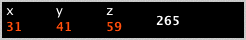
If the mouse cursor is within the bounds of the active viewer's image, its coordinate (orange) and the image value at that coordinate (white) will be displayed here. If an overlay is selected, the image value will represent that of the overlay image. The coordinate format depends on the currently selected coordinate type.
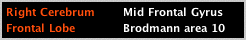
Anatomical Label Display. This display area will be visible when an atlas is selected. If the coordinate is in range, it will display up to four labels: orange being gross anatomical labels and white being finer anatomical labels. See Select Atlas for more information.
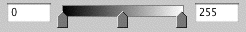
Window Controls. The left value represents the screen minimum or what value will appear completely black. The right value represents the screen maximum or what value will appear completely white. The sliders can be used to dynamically adjust the settings within this range. Moving the middle slider adjusts both end-sliders equally in the same direction (brightness). Double-clicking an end-slider and moving it will adjust both end-sliders equally in opposite directions (contrast). Double-clicking the middle slider will set the slider positions to their maximum and minimum extents. Triple-clicking the middle slider will reset the sliders to the stored display range. If an overlay is selected, these values will represent that of the overlay image. The actual color mapping will depend on the currently selected color table. Depending on Options Menu settings, window changes may affect the active viewer only or all viewers.

 Image Stack. All images loaded in the currently active viewer are organized here and can be accessed via an ordered drop-down list. The icon displayed on the image stack button represents the color table of the currently selected image. The stack order of overlay icons represents the stack order of overlay images, with the base image icon always at the bottom. Hovering the mouse cursor over an item in the drop-down list will open a sub-menu with the following options:
- Get Info. Shows overlay image file name. Click the pop-up to run Image Info for this image.
- Show/Hide. Toggle the visibility of the overlay.
- Remove. Remove this overlay from the slice viewer.
- Color Table. Select from built-in or user-generated color tables.
- Transparency. Set the transparency of the overlay.
- Transform. Apply a Talairach-to-MNI or MNI-to-Talairach transform.
- Load Negatives. Load a second overlay in the negative range from the same data volume.
- Move Up/Move Down. Changes the position of the overlay in the image stack. The base image is always at the bottom of the stack.
 Transform Selection. Toggle the image transform on/off. See the Transform tool for more information.
Coordinate Type Selection. The coordinate type can be selected here. This is a global feature.
 Image Space. The coordinates will be displayed as voxel index location relative to the left, anterior, superior corner of the image. This is the appropriate coordinate space to use if you are overlaying images of the same dimensions.

 World Space. The coordinates will be displayed as millimeter distances from the origin. This is the appropriate coordinate space to use if you are overlaying images of different dimensions.
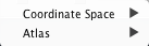
World Space Options. Hovering the mouse over the world space icon, will display a popup with two options:
- Coordinate Space. If an image contains a transform into a standard space, you can select which transform to apply here.
- Atlas. Select which atlas to use here.

 Single Slice Mode Toggle. The single-slice mode can be toggled with this button. When in multi-slice mode, the entire region-of-interest volume is affected. When in single-slice mode, only the main slice view is affected. This mode is considered for most all menu-driven ROI operations, including ROI clipboard operations. This is a global feature.
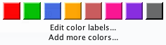
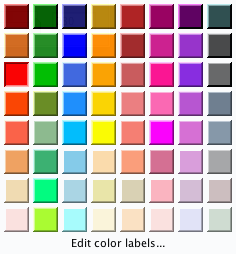 ROI Color Selection. The ROI color picker (seen at left) is used to select the current ROI color. By default, 8 color options are provided. Click 'Add more colors' to double the number of colors. The number of colors can be doubled up to a maximum of 64 (see image at right).
Currently used colors are displayed with a lowered button state (see the first column, third row in the image to the right).
If multiple ROI colors overlap in a slice view, the current ROI color, selected here, will be displayed on top of all other colors.
ROI Tool Selection. The current ROI tool can be selected here via a drop-down list. This is a global feature.

 Navigation/Selection Mode. This mode is required to navigate the image volume as well as individually select, move, and reshape ROIs. Press [Shift] to toggle ROI selection box mode.
Paint Tools. With these tools, an ROI can be created and edited as with a paint brush. Options are provided to set the paint brush tool shape and size. The size of the tool can be changed from the keyboard using the [Minus] and [Plus] keys. If the Set Explicit Value Range option is used, only those voxels with values in range will be affected. The number of slices that are affected is determined by the Set Tool Slice Range option.

 Edit Mode. This is a hybrid of Erase Mode and Paint Mode. If the mouse cursor is pressed and dragged starting outside of the ROI, it will behave as Erase Mode. If the mouse cursor is pressed and dragged starting inside of the ROI, it will behave as Paint Mode.

 Paint Mode. This mode can be used to fill ROI area.

 Erase Mode. This mode can be used to erase ROI area.
Trace Tools. With these tools, an ROI can be created by tracing a region. If the Set Explicit Value Range option is used, only those voxels with values in range will be affected.
 Draw Region as Rectangle. This tool can be used to trace a new rectangular ROI.
 Draw Region as Ellipse. This tool can be used to trace a new ellipsoidal ROI.
 Trace Region. This tool can be used to trace new ROIs of any shape. The tool can either be dragged across the image or clicked in a point-to-point fashion. The polygon will be closed automatically once the end point reaches near to the start point. The new ROI will not be generated until the polygon is closed. Use [Backspace] or [Delete] to remove a polygon in progress.
 Trace Line. This tool can be used to trace new ROI lines. It can either be dragged across the image or clicked in a point-to-point fashion. The line can either be closed or open and will be closed automatically once the end point comes near to the start point. Use [Enter] to commit a non-closed line in progress. Use [Backspace] or [Delete] to remove a line in progress.
A number of additional options are available while in line mode. Double-clicking an open line end-point can be used to continue the line (and can be closed if the extension reaches the other end-point). Double-clicking a point of a closed line will break the line at that point. Right-clicking the start point of a line opens a context menu with options such as smoothing and performing a convex hull.
Individual points can be grabbed and moved, as well new points can be added by grabbing the line between already existing points. While a point is grabbed, [Backspace] or [Delete] can be used to delete it.
 Add Points. This tool can be used to make individual ROI points.
Magic Wand Tools. With these tools, sub-regions of ROIs can be selected and operated on. To select a sub-region, first set the appropriate current ROI color, then click the sub-region of that ROI with the magic wand tool. Sub-regions may be selected in 2D or 3D depending on the single-slice mode.
 Add Region. This tool can be used to construct an ROI. Clicking an image voxel will include it in the current ROI as well as any neighboring voxels of the same or near value. An option is provided to set the relative range, or tolerance, of this tool. Note, an explicit range will supersede this relative range.
 Preserve Region. This tool can be used to select sub-regions of ROIs for preservation, while deleting all ROI area outside of the selected region.
 Erase Region. This tool can be used to delete selected sub-regions of a ROI.
 Dilate/Erode Region. Using this tool, selected sub-regions can be dilated (default) or eroded (pressing [Shift]).
 Copy Region. This tool can be used to copy selected sub-regions onto the clipboard.
 Image Capture. Depending on which window is currently active, the main slice view or the surface view can be captured and saved to disk as an image. The file is named automatically based on the image file name and will increment a four-digit number if the file already exists. See the Screen Capture section of Preferences for more information. Alternatively, pressing [Shift] while clicking the camera button will open a file dialog that can be used to select a destination folder and file name.